笔记栏文章声明
Warning
笔记栏所记录文章往往未经校对,或包含错误认识或偏颇观点,亦或采用只有自身能够理解的记录。
Rendering Shadows
Shadow Settings
需要建立一个ShadowSettings类以保存shadowmap属性,如最远的距离maxDistance和纹理大小。
把ShadowSettings作为[SerializedField]成员添加到CustomRenderPipelineAsset里去(chapter 1),则可以通过inspector调节其属性。
Passing Along Settings
把ShadowSettings结构体层层传递,最后传递给Camera.Render方法,并传递给lighing.Setup和Cull方法。
Cull方法中out ScriptableCullingParameters p中可以填充Mathf.Min(shadowDistance,camera.farClipPlane)的值,对于相机可视范围以外渲染阴影是无意义的。
Shadows Class
单独采用一个类Shadow来管理shadowmap相关渲染的过程,并在Lighing的Setup函数里设置好这个类(逻辑上Shadows属于Light)。
Lights with Shadows
函数bool cullingResults.GetShadowCasterBounds(visibleLightIndex, out Bounds b)可以用于验证index的visiableLight是否能够照亮场景内能够投射阴影的物体。
返回false如果这个光源无法照亮。
并且需要筛选light.shadow模式和light.shadowStrength.
Creating the Shadow Atlas
在light.Render()方法里调用shadows.Render()方法,用于生成shadowmaps。
Shadows First
shadowmap应该先从光源渲染一次,再从相机渲染一次。所以调整camera.Render主循环,先调用Light.Setup->shadows.Render(),再调用camera.Setup() -> draw...。
Rendering
调用链条
绘制阴影需要先生成ShadowDrawingSettings,需要cullingResults。
        var light = _shadowedDirectionalLights[index];
        var shadowSettings = new ShadowDrawingSettings(
            _cullingResults, light.visibleLightIndex);
由于Directional Light没有位置,只有方向,所以其view和projective与普通的投影相机不同。Unity提供了一个函数cullingResults.ComputeDirectionalShadowMatricesAndCullingPrimitives以计算,其九个参数下文另说。
Shadow Caster Pass
添加一个ShadowCaster tag的模式,并添加ColorMask 0在前面,表示不需要渲染颜色。(shadowmap无颜色)
创建一个普通的ShadowCaster的shader。
Multiple Lights
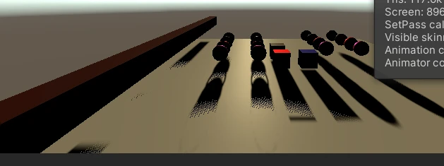
多个光源的时候的shadowmaps会叠加到一起,因此在渲染的时候需要调整viewport,其viewport的参数为纹理的一个Rect,以左上角的坐标开始(0,0),后两个参数为viewport的大小。
        int tiles = shadowDirectionalLightCount * _shadowSettings.directional.cascadeCount;
        //light = 3, cascade = 4, tile = 3 * 4 = 12
        //if tiles == 1, split = 1
        //if tiles == 2or 3, split = 2
        //if tiles >= 4, split = 4
        //max 16 tiles
        int split = tiles <= 1 ? 1 : tiles <= 4 ? 2 : 4
        int tileSize = _atlasSize / split;
    Vector2 SetTileViewport(int index, int split, float tileSize)
    {
        //split = 2,index =3, offset = (1,1)
        //split = 2,index =4, offset = (1,2)
        Vector2 offset = new Vector2(index % split, index / split);
        _cmdbuf.SetViewport(new Rect(offset.x * tileSize, offset.y * tileSize,
            tileSize, tileSize));
        return offset;
    }
Sampling Shadows
Shadow Matrices
需要保存Shadow的project * view矩阵,以在camera渲染的时候把世界坐标转换到Light坐标系下的坐标。
但是我们现在在用Atlas的形式,所以还需要把矩阵进一步转换,其具体的转换见注释。
 Matrix4x4 ConvertLightMatrixToAtlasMatrix(Matrix4x4 pv, Vector2 offset, int split)
    {
        //由于directionalLight的projective 矩阵是ortho投影,所以其不需要进行透视除法
        // 因此乘出来的就是在[-1,1范围内]
        //pv * world-space  = clip-space coords[-1,1]
        //but we now need atlas texture coords
        //so we have to add another transformation to transfer clip-space coords to atlas coords
        //if we handle revers-z here we don't need to handle it in shader

        //to be verified:   the pv matrix has reverse z
        Matrix4x4 t3 = Matrix4x4.identity;
        if (SystemInfo.usesReversedZBuffer)
        {
            t3.m20 *= -1.0f;
            t3.m21 *= -1.0f;
            t3.m22 *= -1.0f;
            t3.m23 *= -1.0f;
        }

        Matrix4x4 t1 = Matrix4x4.Translate(new Vector3(0.5f, 0.5f, 0.5f));
        Matrix4x4 t2 = Matrix4x4.Scale(new Vector3(0.5f, 0.5f, 0.5f));

        //now we transform the clip space to [0,1]
        Matrix4x4 tmp = t1 * t2 * t3 * pv;
        // then we transform the [0,1] to atlas space
        float scale = 1.0f / split;

        //for atlas 4th tile, translate is [1,1]
        //after scale the uv will be [0.5,0.5], correct for atlas
        t1 = Matrix4x4.Translate(new Vector3(offset.x, offset.y, 0.0f));
        t2 = Matrix4x4.Scale(new Vector3(scale, scale, 1.0f));
        return t2 * t1 * tmp;
    }
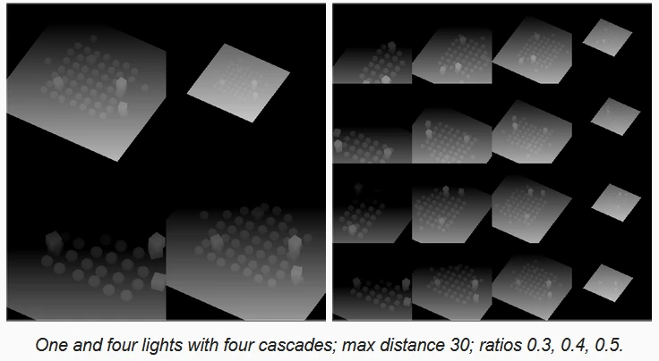
Cascaded Shadow Maps
把不同的物体渲染超过多次,但是每次渲染的时候用不同的矩阵,所以会有多个tiles在shadowmaps上,采样时采样最合适的tile。
Settings
Unity内建支持4个cascade,对于directional Light。
首先需要设置cascade ratio,每个cascade覆盖整个阴影区域的一部分,随着距离增加ratio应该越来越大(覆盖越来愈大的范围)。
Rendering Cascades
由于每个cascade渲染的时候pv矩阵不同,因此需要额外的矩阵数组。
最多4个Directional Light,每个Light 4个cascade,需要16个矩阵。
pv矩阵的生成不需要手动算,unity提供的函数,但是需要我们把cascade index,总共的数量和ratios传进去。
int cascadeCount = settings.directional.cascadeCount;
		int tileOffset = index * cascadeCount;
		Vector3 ratios = settings.directional.CascadeRatios;

		for (int i = 0; i < cascadeCount; i++) {
			cullingResults.ComputeDirectionalShadowMatricesAndCullingPrimitives(
				light.visibleLightIndex, i, cascadeCount, ratios, tileSize, 0f,
				out Matrix4x4 viewMatrix, out Matrix4x4 projectionMatrix,
				out ShadowSplitData splitData
			);
			shadowSettings.splitData = splitData;
			int tileIndex = tileOffset + i;
			dirShadowMatrices[tileIndex] = ConvertToAtlasMatrix(
				projectionMatrix * viewMatrix,
				SetTileViewport(tileIndex, split, tileSize), split
			);
Culling Sphere
Unity根据提供的ratios来决定culling sphere。
正交矩阵的成像椎体是一个立方体,不同的ratio相当于把这个立方体切割成了几份,为了完整包裹这些立方体,一种方法是culling sphere。
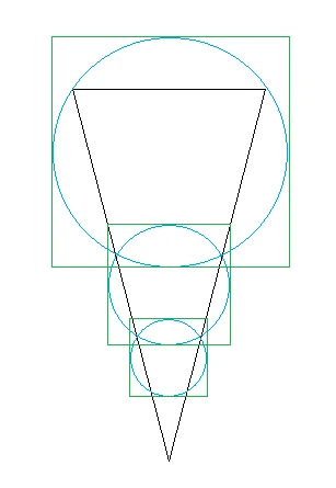
culling Sphere的相关信息(vector4)被保存在splitData.cullingSphere属性中,包含xyz(圆心)和半径w。
Sampling Cascades
在shader里接收culling sphere的信息,注意半径w在传入前被平方以节约计算。
CBUFFER_START(_CustomShadows)
	int _CascadeCount;
	float4 _CascadeCullingSpheres[MAX_CASCADE_COUNT];
    ...
CBUFFER_END
每个像素在着色的时候需要确定其cascadeIndex,判断从哪个cascade取shadowmap(data.tileIndex =_DirectionalLightShadowData[lightIndex].y + shadowData.cascadeIndex;)。
计算cascadeIndex可以遍历像素点的worldSpace到cascade圆心的欧氏距离。从小的cascade到大的cascade,如果点在范围内就取这个cascade。
Culling Shadow Sampling
如果我们超出了_CascadeCount的范围(也就是着色的fragment已经在设置的SHadowMaxDistance以外了),需要直接返回无阴影的结果。
Max Distance
由于Culling Sphere包着立方体,其裁剪的范围并不严格等于设置的 MaxDistance。 如果我们想要严格的裁剪,需要在fshader里比较viewspace的z坐标
surface.depth = -TransformWorldToView(input.positionWS).z; // Unity坐标系遵照OpenGL惯例,在viewspace下其相机面对的方向是负半轴(右手坐标系)
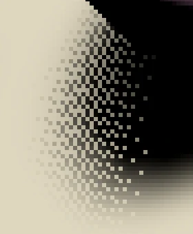
Fading Shadows
直接裁剪会有一个硬过度,可以引入一个参数fade距离,当表面超过这个距离的时候其阴影就会有衰减。
$$saturate\frac{1 - \frac{d}{MaxDistance}}{f})$$
f可以通过滑条控制,这个式子控制shadow.Strength,其strength用于在[1.0, pcf_result]中插值,strength = 0时候其attenuation = 1.0,完全无shadow。
Fading Cascades
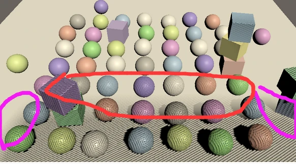
可以使用MaxDistance裁剪在加上culling sphere裁剪,做法类似,在裁剪的边缘加一个过渡带。
紫色部分为cascade的边缘裁剪,红色部分为最大距离裁剪。
Shadow Quality
Bias
unity又提供了一个函数设置Bias,第一个参数是constant bias,第二个参数是slope bias,就是在clip space下ddx和ddy的差值。比如光照正射平面,深度图ddx ddy的差值为0,如果平面是沿着Y轴旋转倾斜的,那么ddx和ddy就不同,倾斜程度越大,相差越大。
buffer.SetGlobalDepthBias(0f, 3f);
一般而言slopbias表现很好,设置个较小的常数(3.0)表示放大这个bias 三倍。
Cascade Data
代码质量提升,把每个Cascade相关的数据整理成一个结构体Struct CascadeData,没什么用。
Normal Bias
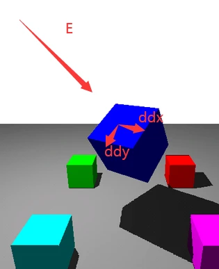
float texelSize = 2f * cullingSphere.w / tileSize; //从相机看过去,culling sphere的圆心在相机正中间,sphere是一个正方形的外接圆,正方向的对角线刚好是sphere 的直径
texelSize= texelSize * 1.414f; //其实我感觉要除以sqrt2才对,不过这只是一个常数差异
float3 normalBias = surfaceWS.normal * _CascadeData[global.cascadeIndex].y;
沿着normal方向,将世界坐标沿着发现方向移动 normalWs * texelSize,离镜头越近,其texelSize越小,normalBias越小(相当于物体在深度图上被扩张了,防止两个物体表面像素在深度图上只占据一个像素导致出现shadow acne)
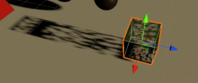
Shadow Pancaking
瑕疵
在渲染shadowmap的时候 Unity会尽可能得把视椎体的近平面往前移动,以提高shadowmap的精度,但是这会带来瑕疵(视椎体外的顶点被剔除导致影子出现瑕疵。)
在shadowcasterpassvertex里,对于在视椎体外的顶点将其投影在视椎体上
#if UNITY_REVERSED_Z
    output.positionCS.z =
        min(output.positionCS.z, output.positionCS.w * UNITY_NEAR_CLIP_VALUE);
#else
    output.positionCS.z =
        max(output.positionCS.z, output.positionCS.w * UNITY_NEAR_CLIP_VALUE);
#endif
设立一个NearPlaneOffset滑条,并在计算ComputeDirectionalShadowMatri.....这个函数里传入,将NearPlane往后拉
cullingResults.ComputeDirectionalShadowMatricesAndCullingPrimitives(
    light.visibleLightIndex, i, cascadeCount, ratios, tileSize,
    light.nearPlaneOffset, out Matrix4x4 viewMatrix,
    out Matrix4x4 projectionMatrix, out ShadowSplitData splitData
);
PCF Filtering
软阴影
SAMPLE_TEXTURE2D_SHADOW宏调用 textureName.SampleCmpLevelZero,在Dx上支持硬件2x2 PCF。
#include "Packages/com.unity.render-pipelines.core/ShaderLibrary/Shadow/ShadowSamplingTent.hlsl"

#if defined(_DIRECTIONAL_PCF3)
	#define DIRECTIONAL_FILTER_SAMPLES 4
	#define DIRECTIONAL_FILTER_SETUP SampleShadow_ComputeSamples_Tent_3x3
#endif
Info
Q: 看一下四个tap的分布
A: 深入进去看了下代码大概核心代码是
//确保中心点在最近的纹素的左上角。
real2 centerOfFetchesInTexelSpace = floor(tentCenterInTexelSpace + 0.5);
//用一个没看懂的算法计算四采样点的weights
real2 fetchesOffsetsU = texelsWeightsU.yw / fetchesWeightsU.xy + real2(-1.5,0.5);
real2 fetchesOffsetsV = texelsWeightsV.yw / fetchesWeightsV.xy + real2(-1.5,0.5);
//考虑到采样权重都是正数,而且采样权重都不会超过1,所以姑且理解为亚像素级别上偏移一下四个采样点。。
fetchesUV[0] = bilinearFetchOrigin + real2(fetchesOffsetsU.x, fetchesOffsetsV.x);
fetchesUV[1] = bilinearFetchOrigin + real2(fetchesOffsetsU.y, fetchesOffsetsV.x);
fetchesUV[2] = bilinearFetchOrigin + real2(fetchesOffsetsU.x, fetchesOffsetsV.y);
fetchesUV[3] = bilinearFetchOrigin + real2(fetchesOffsetsU.y, fetchesOffsetsV.y);
所以结论就是以uv坐标所对应的纹素的左上角为中心,以周围的[±1.5,±0.5]的四个采样点,并且加上一点亚像素偏移。
以确保bilinear sampler能够采样到周围的像素,但我感觉bilinear的影响范围应该超过了9x9范围了。
灵魂示意图如图所示。

Fig. 4个采样点示意图。
绿色为中心,红色为采样点,箭头方向为亚像素偏移方向
Blending Cascades
软阴影在不同的sphere的采样边界会有硬边,因为纹理大小一样但是不同的物体在cascade上成像不一样,其分辨率精度不同。
加上软阴影落在sphere边界外的采样点会被剔除,导致边界不自然过度。
可以加一个Blend参数,在cascade的边界设置一个blend参数,当距离圆心一定距离以后,blend系数就开始 < 1。 在计算light的Atenuation的时候,如果blend系数小于1,说明上一个着色点在cascade sphere的边界处,那么再根据这个着色点再采样下一个cascade的shadowmap(不同cascade sphere有重合),然后用blend系数进行插值。
可以获得柔滑过度,缺点是在过渡带要采样两次shadowmap和进行两次计算。
Dithered Transition
每个像素点生成一个噪声值([0,1)),对blend < noise的像素(处于边界),采样下一个cascade shadowmap,利用了人眼对噪声不敏感的特点。
Culling Bias
splitData.shadowCascadeBlendCullingFactor = 1f;
shadowSettings.splitData = splitData;
对于cascade来说,不同的物体会被重复渲染N次。
如果我们确认一些阴影可以在小的cascade中取得,那么大的cascade就不用渲染这些物体。
shadowCascadeBlendCullingFactor用来控制Unity的剔除方式,值越高,剔除越激进。
		float cullingFactor =
			Mathf.Max(0f, 0.8f - settings.directional.cascadeFade);

		for (int i = 0; i < cascadeCount; i++) {
			…
			splitData.shadowCascadeBlendCullingFactor = cullingFactor;
			…
		}
做成和cascadeFade有关的变量,因为cascadeFade控制不同cascade之间的过度,如果cascadeFade=0,那么其过渡带为0,为硬过度,那么就没有同时采样两个cascade的fragment,所以i剔除就可以更激进一点。
Transparency
Chapter 3 Directional Lights中我们实现了半透明材质,其支持两种模式,一种是透明(transparent),一种是clipping,丢弃透明度低于超参数cutoff的值。
ShadowCaster这个Pass无视半透明材质的ZWrite选项,也就是shadowmap上会记录半透明物体的深度,所以能渲染阴影,但是只有在Clipping模式下才正确,不能通过测试的像素被丢弃了,所以在shadowmap上记录的是正确的深度。
clip模式
就是之前的clip
注意
在Shader的Keyword的定义方式(Unity Properties惯用)
[KeywordEnum(On, Clip, Dither, Off)] _Shadow ("Shadows", Float) = 0
[Toggle(_RECEIVE_SHADOWS)] _ReceiveShadows ("Receive Shadows", Float) = 1
第一个会在Properties选中的时候切换_Shadow_On, _Shadow_Clip...等宏
第二个会Toggle _RECEIVE_SHADOWS这个keyword。
名字一定要和shader里的#pragma shader_feature _ _SHADOW_CLIP这种对上
Dither模式
   #elif defined(_SHADOW_DITHER)
       float dither = InterleavedGradientNoise(input.posCS.xy,0);
       clip(baseColor.a - dither);
   #endif
运动时会遭受严重的抖动,没法用,只适合静止相机的场景
No Shadows
对单个物体关闭阴影可以在MeshRender的Cast Shadows这里关掉。
如果要对整个材质关闭阴影,可以禁用材质的ShadowCaster这个Pass。
	void SetShadowCasterPass () {
	  // 查询这个shader绑定的所有的material的_Shadow Property
		MaterialProperty shadows = FindProperty("_Shadow", properties, false);
		if (shadows == null || shadows.hasMixedValue) {
			return;
		}
		// 只有在ShadowMode != off的时候才打开ShadowCaster
		// Shader里定义_Shadow Property的顺序要和C#里的enum的顺序相同
		bool enabled = shadows.floatValue < (float)ShadowMode.Off;
		foreach (Material m in materials) {
			m.SetShaderPassEnabled("ShadowCaster", enabled);
		}
	}
Editor提供两个API,可以检测在这个区间内是否进行过API操作(IMGUI无敌)
	public override void OnGUI (
		MaterialEditor materialEditor, MaterialProperty[] properties
	) {
		EditorGUI.BeginChangeCheck();
		…
		if (EditorGUI.EndChangeCheck()) {
			SetShadowCasterPass();
		}
	}